Für eine deutsche Übersetzung Klicken Sie hier
For more information about the product follow the respective links:
- User manual
- Datasheet
- CE Declaration
- Flyer
- Using with POPP Hub
- Using with Z-Wave.me
- Using with Fibaro Home Center Lite
- Using with Fibaro Home Center 3
Quick start.
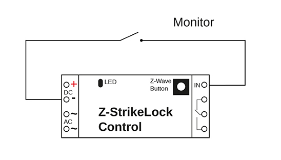
Getting your Strike Lock Control up will require wiring it into your application and linking it to your Z-Wave network. The following instructions tell you how to wire then add your Strike Lock Control to your Z-Wave network using an existing gateway.
Strike Lock Control does not support unsecure Z-Wave pairing.
1. Installation:
There are many styles of installation for Strike Lock Control, we will list all available wiring configurations for Strike Lock Control.
No existing installation of an electrical door opener and no AC power on the spot.
- Find a place for installing your battery and Strike Lock Control nearby your application.
No existing installation of an electrical door opener but dedicated AC Power.
You may find AC power on the spot if the door is near a traditional door bell button that is powered by a conventional transformer. In this case you will have to install the mechanical strike look and find a dry place for the strike lock control. The distance between the transformer and the strike lock control and between the strike lock control and the strike depends on the quality of the transformer and the quality of the wires used. You may orientate on the distances between the existing door bell button and the transformer (usually placed inside the mains distribution panel).
- Find a dry place to install Strike Lock Control (unit should never get wet).
- Connect your AC 8-12V transformer that connects to your current Strike Lock to the upper VAC connector.
- Disconnect the other end of Strike Lock power connecting to the bottom most VAC connector.
- Bridge the connection in Step 3 between the Bottom VAC terminal and the bottom most Strike Lock connector terminal.
- Connect the Strike Locks other terminal to the middle Strike Lock connector terminal on Strike Lock Controller.
Existing traditional analog door bell installation.
Existing door bell installations typically connects the door bell button and the bell using two wire cables to the mains distribution panel where the AC transformer is placed. The image below shows how to change this existing cabling to power the strike lock in parallel.
Existing (multi user) Intercom system with integrated door opener
Most multi-floor apartments are equipped with an audio communication between the main door and the apartments to identify visitors. These systems usually contain a method of open the the front door using a button on the Intercom system. Communication between the different terminals inside the apartments and a central control are of proprietary nature. The strike lock will then control from the central controller device using the intercoms two dedicated wires.
The Popp Strike lock can be used in this type of installation independent of the type of the Intercom solution and without interfering the existing Intercom infrastructure. The system will work with both battery operation and AC power supply (image shows battery solution only, please see image 2 for VAC wiring).
Mechanical Installation of the Strike Lock.
- Remove the existing door plate by unscrewing it with your screwdriver. Be careful not to strip the screws as this will make removal much more difficult.
- Now you have two options. The strike lock is connected to the door strike using two screws in a distance of 55 cm. This is a standardized distance and the two holes should already be available on almost all plates in the market. If they are not available you have to drill two holes of diameter of 4 mm in equal distance from the cut out that accommodates the door latch. The cut-out can be done using a simple metal saw or a dremel.
- Find a plate that already has the cut-outs to fit the strike lock
- Cut your existing plate to accommodate the strike lock.
- Make sure there is enough room behind the plate so that the look fits in. Our strike look is particularly small so the required space allocation is only 16,6 mm width and 26 mm deep.
- Decide where to place the control electronics. You can place it near the strike using short wires or place is next to your power supply using longer wires.

2. Pair Strike Lock Control using an existing gateway:
- Place your gateway or controller into Z-Wave secure pair or secure inclusion mode. (Please refer to your controller/gateway manual on how to do this)
- Press and hold the Z-Wave Button for 1 second.
- Now release the Z-Wave Button.
- Your gateway should confirm if Strike Lock Control is successfully included into your network.
Only for version 1.03 or lower.
Automated Close after Opening (Parameter number 0, Size 1).
Value | Description |
0 | No automated close after command ‘open’ |
1 - 127 | Close again after x seconds (Default 3) |
Was this article helpful?
That’s Great!
Thank you for your feedback
Sorry! We couldn't be helpful
Thank you for your feedback
Feedback sent
We appreciate your effort and will try to fix the article